

Views: 0 Author: Site Editor Publish Time: 2026-07-21 Origin: Site


High-precision manufacturing hinges on true concentricity. You must align the rotational axis perfectly with machined features to ensure success. Failing to do this results in expensive scrap, assembly failures, and compromised part performance.
Traditional multi-machine setups inherently introduce stack-up tolerances. Moving a part from a lathe to a mill destroys your baseline accuracy. For complex parts, relying on manual refixturing becomes a massive business risk.
This guide breaks down how advanced turning centers engineer out concentricity errors. We will examine the business case for single-setup machining and outline immediate ROI benefits. You will also learn the criteria for evaluating machine capabilities for your production floor.
Stack-up error is the primary enemy of concentricity: Every time a part is refixtured, baseline datum accuracy degrades.
Machine rigidity and thermal stability dictate baseline capability: A CNC lathe cannot produce parts more concentric than its own spindle runout.
Single-setup architecture is the definitive solution: Adopting a CNC Mill-Turn Machine mitigates operator handling risks and mathematically reduces deviation.
Automated part transfer preserves datums: A Twin-Spindle CNC Mill-Turn Machine allows for back-end machining while maintaining the original centerline reference.
Defining success in modern machining requires moving beyond basic dimensional tolerances. You must evaluate Total Indicator Reading (TIR) and its direct impact on dynamic part balance. Consider aerospace shafts or medical bone screws. In these applications, a slight concentricity deviation causes severe vibration or catastrophic biological failure. You cannot inspect quality into a part; you must machine it into the foundation.
Multi-setup routing carries severe hidden costs. Moving parts across different workstations drains profitability rapidly.
Excessive Labor Costs: Dialing in parts on secondary machines takes hours of highly paid operator time.
Quality Assurance Bottlenecks: Inspectors must constantly verify datums after every machine move, slowing down throughput.
Increased Scrap Rates: Human error during manual part flips inevitably leads to misaligned workpieces and rejected batches.
Relying on "hero operators" introduces extreme scalability risks. You might have a veteran machinist who can brilliantly shim and indicate parts to hit tight TIR specs. However, this is not a scalable production strategy. When they take a day off, your production stops. True scalability demands relying on capable machine architecture rather than manual intervention.
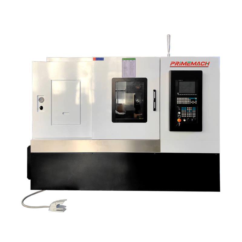
A rigid CNC Lathe relies on its underlying mechanics to maintain tight tolerances. Spindle architecture dictates the absolute limit of your concentricity. Angular contact bearings handle both radial and axial loads efficiently. For ultra-precision applications, hydrostatic spindles provide a pressurized fluid film. They eliminate metal-to-metal contact completely, minimizing radial play and achieving sub-micron runout limits.
Extended production runs generate massive amounts of heat. Thermal growth in the casting and spindle headstock pushes the tool off-center. Cutting-edge machines deploy thermal compensation management to combat this. Integrated sensors monitor temperature changes across the machine frame. Sophisticated software algorithms then dynamically offset the X and Z axes to maintain the true centerline. This prevents parts from drifting out of tolerance during a long shift.
Your choice of guideways also dictates rigidity and vibration control.
Guideway Type | Primary Advantage | Vibration Control | Best Application Use Case |
|---|---|---|---|
Box Ways | Maximum Rigidity | Superior Dampening | Heavy interrupted cuts on tough alloys |
Linear Guideways | Micro-Positioning | Moderate Dampening | High-speed rapids and light precision turning |
Adopting a CNC Mill-Turn Machine shifts the production philosophy entirely. Manufacturers call this the "Done-in-One" approach. By consolidating turning and milling operations into a single coordinate system, you eliminate the stack-up errors inherent in manual refixturing. The primary rotational center point remains locked.
Live tooling dynamics provide incredible flexibility. The integration of B-axis and Y-axis kinematics allows cutting tools to approach the workpiece from complex angles. You can execute off-center drilling and complex pocket milling while the main spindle firmly holds the part. Because the workpiece never leaves the chuck, the relationship between the turned diameter and the milled feature remains mathematically perfect.
Evaluating feature-to-outcome benefits reveals immediate process upgrades. Consider polygon turning or rigid tapping. If you perform these operations in one setup, you guarantee 100% phase alignment. Milled flats, cross-holes, and the main turned axis will share exact concentricity. You bypass the daily guessing game of trying to realign a previously turned part inside a standalone milling center.
Using a Twin-Spindle CNC Mill-Turn Machine allows you to automate the entire part lifecycle safely. The mechanics of synchronized handoffs are a marvel of process engineering. The main spindle and the sub-spindle synchronize their RPM and phase angles perfectly. They transfer the part mid-cycle without losing the original zero-point reference.
This automated transfer enables machining the "sixth side" of the part. You can complete intricate back-turning operations while holding onto the previously machined concentric diameter. This strict datum preservation ensures front-to-back TIR stays within microns. Operators never touch the part until the machine drops the finished component into the parts catcher.
However, implementation realities carry specific risks you must manage:
Strict PM Scheduling: Sub-spindle alignment is not infinite. You must adhere strictly to preventative maintenance routines to keep both spindles dead-true.
Post-Crash Realignment: Even minor machine crashes can knock the sub-spindle out of alignment. Mechanical realignment using specialized test bars is mandatory after any collision.
Advanced CAM Requirements: Safely orchestrating collision-free handoffs requires robust CAM software and perfectly dialed-in post-processors. Do not rely on manual conversational programming for complex spindle transfers.
Even a half-million-dollar machine will fail concentricity specs if the workholding is compromised. Workholding remains the weak link in many high-precision setups. You cannot achieve true concentricity if your chuck jaws induce runout before the cutting tool even touches the material.
Understanding when to deploy specific gripping systems is a critical operator reality. Collet systems prove vastly superior for uniform bar stock. They offer 360-degree gripping force and suffer from minimal centrifugal distortion at high RPMs. This keeps the material perfectly centered.
Alternatively, odd-shaped castings require bored soft jaws. Machinists often make a critical mistake here. They bore the jaws without simulating actual clamping pressure. You must bore soft jaws using a dedicated jaw-boring ring. This pre-loads the chuck jaws, mimicking the exact hydraulic pressure they will experience during production. Failing to do this guarantees part runout.
Workholding System | Material Suitability | Centrifugal Distortion Risk | Setup Requirements |
|---|---|---|---|
Collet Chucks | Uniform Bar Stock (Round/Hex) | Extremely Low | Fast changeovers, requires matching collet sizes |
Bored Soft Jaws | Castings, Forgings, Odd Shapes | Moderate to High (RPM dependent) | Requires careful boring under simulated clamping pressure |
Hard Jaws | Rough Stock, First Operations | High | Minimal prep, prone to marring finished surfaces |
Tool wear and tool deflection heavily influence concentricity outcomes. Heavy cutting forces naturally push the part off-center. As inserts wear down, cutting pressure increases, worsening the deflection. For workpieces featuring high Length-to-Diameter (L/D) ratios, utilizing programmable tailstocks or hydraulic steady rests is non-negotiable. These supports counteract tool pressure, keeping the material from bowing away from the insert and preserving true TIR.
Selecting the right multi-tasking equipment requires analyzing your specific part mix. Look closely at your most complex prints. Do they only require simple live tooling for basic cross-holes? Or do they demand full 5-axis simultaneous interpolation to machine sculpted aerospace contours? Matching the machine kinematics to your exact part geometry prevents severe over-purchasing or under-equipping.
Calculate your ROI variables purely based on efficiency gains. Look at the immediate reduction in Work in Process (WIP). Single-setup machining eliminates pallets of half-finished parts sitting on the shop floor. Calculate the eliminated setup times. Instead of tearing down three machines, your operators set up one. Finally, factor in the drastic scrap reduction achieved by removing human handling errors.
Take strict next steps before signing a purchase order:
Request standard test cuts from the machine tool builders.
Demand the NAS 979 standard test to verify dynamic accuracy.
Measure real-world concentricity under actual cutting loads, rather than trusting laser-calibrated static positioning metrics alone.
Maintaining concentricity in complex parts relies entirely on robust process engineering and advanced machine architecture. You can no longer depend solely on the unique skills of a few veteran operators to hit tight TIR limits.
Investing in rigid workholding practices ensures your baseline datums remain true. Upgrading to single-setup technology entirely removes the risks associated with manual part refixturing.
By implementing these systemic changes, manufacturers shift concentricity from a daily guessing game into a predictable, mathematically controlled certainty. Evaluate your floor today, test your current runout variables, and upgrade your process to protect your profit margins.
A: Not automatically. If the drill is not perfectly on-center with the spindle (due to turret misalignment), or if the drill walks upon entry, the hole will be oversized or tapered, violating concentricity. Center drilling and turret alignment checks are required.
A: For parts with a Length-to-Diameter (L/D) ratio greater than 3:1, a programmable tailstock or a hydraulic steady rest is required to counteract tool pressure and prevent the material from bowing away from the insert.
A: While standard CNC lathes can routinely hold 0.0005” (0.012mm) TIR, high-end machines equipped with thermal compensation and precision collet systems can chase tolerances down to 0.0001” (0.0025mm) in controlled environments.


