

Views: 0 Author: Site Editor Publish Time: 2026-09-30 Origin: Site


Machining multi-diameter parts brings immediate challenges in rigidity, concentricity, and tool clearance. If you manage these poorly, production efficiency drops fast. Inefficient operation sequencing, skipping pre-machining job reviews, and generating sub-optimal toolpaths lead directly to excessive cycle times. You also face higher scrap rates from tolerance stacking and a constant risk of tool interference inside the machining envelope. Implementing a strict process plan for Turret Lathe operations gives you predictable cycle times and keeps the spindle turning. A structured approach lays out a clear framework. It helps you evaluate whether upgrading to advanced multi-axis or CNC equipment makes sense for your specific production volume.
Strategic Sequencing: Prioritizing operations from largest to smallest diameters minimizes deflection and maintains workpiece rigidity during heavy material removal.
Configuration Matching: The choice between a standard CNC Turret Lathe, a Heavy-Duty CNC Lathe, or a Vertical Turret Lathe (VTL) depends strictly on part mass, required torque, and batch scalability.
Multi-Tasking Integration: Defining turrets and spindles for combined mill and turn operations in a single setup drastically reduces handling time and tolerance stacking.
Risk Mitigation: Comprehensive CAM simulation and multi-turret synchronization are mandatory to prevent catastrophic tool collisions in high-density machining envelopes.
ROI Drivers: Effective process planning reduces setup changeovers, directly lowering the cost-per-part in both high-volume runs and high-mix environments requiring frequent setups.
Defining the baseline requirements for multi-diameter parts requires a strict focus on concentricity tolerances, surface finish, and preventing part deflection during aggressive roughing. When a workpiece features multiple stepped diameters, cutting forces shift dramatically as the tool moves along the Z-axis. Machinists must account for these shifting forces to prevent chatter, dimensional inaccuracies, and poor surface finishes. Success demands a machine tool capable of absorbing heavy radial and axial loads while maintaining precise tool positioning across varying diameters.
The structural evolution of turning centers shows why specific designs excel at multi-diameter work. An engine lathe requires manual tool changes and constant operator measurement. This makes it highly inefficient for complex, stepped profiles. A capstan lathe improves upon this by mounting a turret on a short ram that slides within a saddle. While faster, the ram-type design lacks the mass required for heavy material removal. The saddle-type design mounts the hexagonal or multi-station turret directly onto the saddle, which moves along the entire length of the machine bed. This structural difference provides superior rigidity. It allows for heavy, interrupted cuts on large diameters without sacrificing dimensional stability.
The multi-station indexing turret serves as the core productivity driver. It eliminates manual tool changes by allowing operators to load an entire sequence of cutting tools into a single rotating unit. Modern turrets use massive curvic couplings that lock the turret face into position with thousands of pounds of hydraulic force. This enables rapid, sequential engagement of turning, facing, drilling, boring, and threading tools. By indexing to the next tool in milliseconds, the machine maintains continuous production flow. On complex multi-diameter parts, a fully populated turret allows the machine to rough turn the main body, index to a grooving tool to cut an undercut, and index again to a threading tool, all within a single automated cycle.
Material properties and workpiece geometry impose strict rigidity constraints. The length-to-diameter (L/D) ratio dictates the necessity for additional support mechanisms. When machining the smallest diameters at the furthest point from the chuck, the workpiece acts as a cantilever beam. High cutting forces push the part away from the cutting tool. This results in tapered diameters and severe chatter.
Length-to-Diameter (L/D) Ratio | Required Support Mechanism | Machining Impact |
|---|---|---|
Under 3:1 | None (Chuck only) | Maximum rigidity, aggressive roughing permitted. |
3:1 to 6:1 | Tailstock with Live Center | Stabilizes the Z-axis extremity, prevents tapering. |
6:1 to 10:1 | Tailstock + Steady Rest | Prevents mid-shaft deflection and harmonic chatter. |
Over 10:1 | Follower Rest / Specialized Setup | Requires light depths of cut and specialized insert geometries. |
Before any metal is cut, the production team must execute a comprehensive pre-machining job review. This review maps out every step of the manufacturing process. It transforms a raw blueprint into an actionable sequence of machine movements. Skipping this step guarantees inefficiencies on the shop floor. The review must identify critical datums, establish the required surface finishes for each stepped diameter, and allocate specific operations to primary and sub-spindles. By balancing cycle times across multiple spindles, programmers minimize idle turret states and maximize overall machine throughput.
Standard progression for a multi-diameter shaft follows a strict, logical sequence designed to maximize part stability. The sequence typically proceeds as follows:
Facing the raw stock to establish a clean Z-axis zero reference.
Center drilling to provide a location for tailstock engagement.
Rough turning all diameters, strictly moving from the largest diameter to the smallest.
Finish turning the entire profile to final dimensional tolerances.
Executing secondary features like grooving, undercutting, and threading.
Parting off the finished component.
The engineering rationale behind roughing from largest to smallest diameter is rooted in material stress and rigidity. The largest diameter provides the maximum core strength for the workpiece. By roughing the larger sections first, the part retains its bulk mass and stiffness to resist cutting forces. If a machinist turns the smallest diameter first, subsequent heavy roughing cuts on the larger diameters induce massive vibration through the weakened, narrow section. This leads to immediate part failure or severe tolerance deviation. Roughing all sections before applying finish passes also relieves internal material stresses. This ensures dimensional stability during the final precision cuts.
Modern manufacturing relies on continuous, software-driven toolpaths. Computer-Aided Manufacturing (CAM) software allows programmers to utilize canned cycles, such as G71 and G72, for highly efficient material removal. A G71 roughing cycle automatically calculates the depth of cut, feed rate, and retract motions required to clear material from a stepped profile based on a few lines of code defining the final geometry. This eliminates the need to program every single pass manually. It reduces programming time and minimizes the risk of coding errors.
When dealing with complex profiles, programmers must choose between Type I and Type II roughing cycles. Type I is used for monotonic profiles where the diameter consistently decreases or increases. Type II allows for pockets and undercuts within the roughing cycle, commanding the tool to dip into recesses. Selecting the right cycle prevents tool breakage and optimizes chip evacuation.
Defining turrets and spindles within the CAM environment is critical for parts requiring combined mill and turn operations. When utilizing live tooling, programmers must accurately model the machine kinematics. This allows the software to generate toolpaths for cross-holes, flats, or keyways on the various stepped diameters. Proper CAM integration ensures that the C-axis (spindle rotation) and Y-axis (off-center milling) synchronize perfectly with the X and Z axes. This enables complex geometry generation in a single setup.
Chucking methods directly impact the achievable concentricity across multiple diameters. The selection depends heavily on raw material consistency and the required precision.
Collet Chucks: Ideal for cold-rolled bar stock with consistent outer diameters. They provide 360-degree gripping force, excellent concentricity, and rapid clamping times.
3-Jaw Chucks: The standard for general-purpose turning. They handle a wide range of sizes but may introduce slight runout depending on jaw condition and scroll wear. Soft jaws can be bored to exact part diameters to improve concentricity on second operations.
4-Jaw Independent Chucks: Required for irregular stock, castings, or when absolute zero runout is demanded. Each jaw is indicated independently, offering maximum precision at the cost of longer setup times.
For continuous production cycles, integrating automated bar feeders standardizes the setup process. Bar feeders push raw material through the spindle bore after each parting operation, allowing the machine to run unattended. This requires precise programming of the bar pull cycle and strict management of tool wear limits to prevent scrapped parts during lights-out manufacturing.
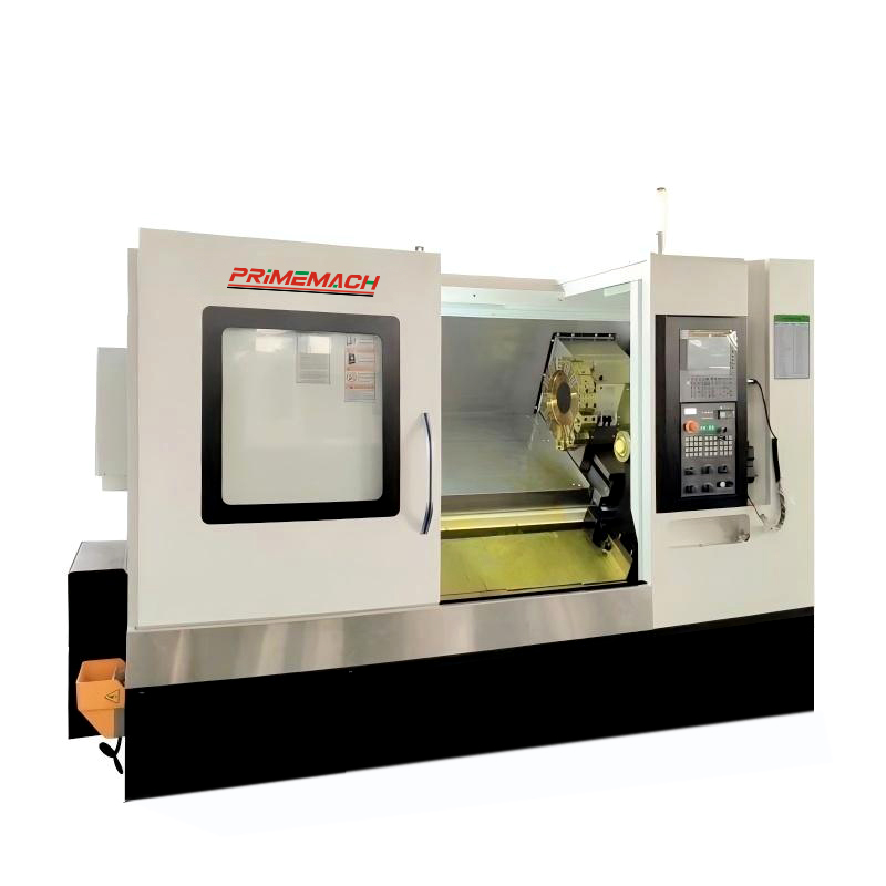
Selecting the correct machine architecture dictates the profitability of the production run. The manual intervention required on traditional capstan or manual lathes limits their utility to repair work, prototyping, or extremely low-volume batches. Operators must physically index the turret, engage feeds, and measure intermediate diameters. In contrast, a modern CNC Turret Lathe automates these processes, delivering repeatable precision and continuous operation. The threshold for CNC equipment is typically crossed when batch sizes exceed 20 to 50 pieces, or when the complexity of the multi-diameter profile makes manual execution too slow and error-prone.
When scaling up to large-scale, high-mass multi-diameter shafts—such as those found in the aerospace, energy, and oil and gas sectors—standard equipment fails. These applications require a Heavy-Duty CNC Lathe. The operational envelope of these machines is defined by high-torque geared spindles capable of turning massive components at low RPMs. They utilize massive box guideways that dampen the extreme vibrations generated by deep depths of cut in tough alloys like Inconel or 4140 steel. Unlike linear guideways built for speed, box ways provide the surface area contact needed to absorb heavy radial loads.
Horizontal heavy-duty turning is standard for long shafts, but Vertical Turret Lathes (VTLs) provide a distinct advantage for specific geometries. VTLs orient the spindle vertically, turning the chuck into a rotating table. This design uses gravity to aid in seating heavy, large-diameter workpieces, such as massive pipe flanges, pump housings, or aerospace turbine discs. By eliminating the cantilever effect found in horizontal turning, VTLs provide unmatched power and precision for large-scale, heavy-mass machining. They allow for aggressive material removal without distorting the workpiece.
High-volume production environments benefit massively from multi-turret machine configurations. Machines equipped with upper and lower turrets allow for simultaneous roughing and finishing. Alternatively, programmers can utilize pinch turning, where two tools engage the workpiece simultaneously from opposite sides. Pinch turning balances the radial cutting forces. This effectively cancels out part deflection and allows for double the feed rate on long, slender multi-diameter shafts.
Driving multi-tasking and multi-axis operations safely requires advanced multi-channel CAM software. Programmers must manage wait codes (sync codes) to ensure the upper turret does not collide with the lower turret or the sub-spindle. The programming complexity increases exponentially. It requires highly skilled personnel to verify tool clearances, manage chip evacuation paths, and optimize the timing of simultaneous cutting operations.
Process planning requires balancing upfront engineering time against long-term production efficiency. The inverse relationship between initial setup time and per-part cycle time savings dictates shop floor strategy. In high-mix environments where a machinist manages 15 to 20 different setups a week, spending hours optimizing a toolpath for a 10-piece run is counterproductive. However, for a 5,000-piece run, shaving 10 seconds off the cycle time through aggressive optimization yields massive profitability.
To manage frequent changeovers, shops must determine the break-even point for utilizing quick-change tooling systems. While these systems require higher initial capital, they allow operators to swap pre-measured cutting heads in seconds. This maintains turret accuracy without re-touching tool offsets. It drastically reduces machine downtime between different multi-diameter part jobs.
Production Environment | Setup Strategy | Tooling Preference | Primary Goal |
|---|---|---|---|
High-Mix / Low-Volume | Standardized turret layouts, flexible workholding (3-jaw). | Standard off-the-shelf carbide inserts (CNMG, WNMG). | Minimize setup time and programming overhead. |
Low-Mix / High-Volume | Dedicated setups, custom bored soft jaws, automated bar feeding. | Custom form tools, combined drill/countersinks. | Minimize per-part cycle time and maximize throughput. |
Large-Scale / Heavy Mass | Crane-assisted loading, independent 4-jaw chucks. | Heavy-duty roughing inserts, vibration-dampening boring bars. | Maximize material removal rates safely. |
Evaluating tooling capital versus cycle time reduction is a constant engineering challenge. Investing in specialized multi-function tools, such as a combined drill and countersink or a custom form tool that cuts three diameters simultaneously, saves valuable turret stations and reduces indexing time. However, these custom tools carry long lead times and high replacement costs. Standard off-the-shelf carbide inserts are cheaper and readily available. They require more turret stations and longer cycle times to generate complex profiles, but offer flexibility across multiple jobs.
Facility requirements also influence overall value when upgrading equipment. Installing a heavy-duty turning center or a VTL requires significant infrastructure planning. These machines demand isolated, reinforced concrete foundations to prevent ground-borne vibrations from affecting surface finishes. Furthermore, the massive volume of chips generated requires automated chip evacuation systems and high-pressure coolant delivery to manage heat and clear the cutting zone. Facility managers must also audit power availability, as high-torque spindles draw substantial amperage during aggressive roughing cycles.
Executing multi-diameter process plans introduces specific operational risks that must be mitigated through strict engineering controls. The most immediate threat in high-density machining envelopes is tool interference. When utilizing boring bars, long drills, or extended live tooling alongside standard turning tools, the risk of the turret colliding with the chuck, tailstock, or the workpiece itself is high.
Digital twin simulations and dry runs are mandatory mitigation steps. Programmers must run the generated G-code through verification software that accurately models the machine kinematics, tool lengths, and fixture dimensions. This software detects collisions in the virtual environment before they cause catastrophic physical damage on the shop floor. Following simulation, operators must execute a dry run. They run the program in single-block mode with the rapid overrides turned down and no material in the chuck to visually verify tool clearances.
Operator skill and safety remain critical concerns, particularly in high-frequency setup environments. Handling multi-diameter parts during frequent changeovers exposes operators to sharp edges and burrs. Minor cuts and lacerations are common injuries when operators manually intervene to deburr parts or clear stringy chips. To mitigate this, process plans must enforce programmed, in-process automated deburring cycles. Utilizing specialized deburring tools or chamfering passes within the CNC program eliminates the need for manual edge-breaking. This protects the operator and ensures consistent part quality.
Tolerance stacking presents a severe quality risk when machining multiple diameters. This occurs when improper datum selection causes dimensional errors to compound across the workpiece. If a programmer references the length of Diameter C based on the shoulder of Diameter B, and Diameter B was referenced from Diameter A, any slight error in A or B will stack. This pushes Diameter C out of tolerance. Process planning frameworks must establish a single, reliable reference zero. This is typically the main spindle face or a primary machined shoulder. You must dimension all subsequent features from that single datum to prevent compounded errors.
Conduct a formal time study on a benchmark multi-diameter part to identify specific bottlenecks in your current operation sequence.
Standardize your turret layouts for high-mix environments to reduce tool changeover times between jobs.
Implement digital twin simulation software to verify complex toolpaths and eliminate the risk of turret collisions.
Request CAM cycle time estimates from machine tool builders using your specific part models before committing to new equipment purchases.
Evaluate facility readiness, specifically focusing on foundation stability and automated chip management, prior to installing heavy-duty machinery.
A: The primary advantage is the elimination of manual tool changes. A CNC turning center provides repeatable indexing precision, the structural rigidity of a saddle-mounted turret, and the ability to execute complex, continuous toolpaths automatically. This drastically reduces cycle times and operator intervention.
A: Always machine from the largest diameter to the smallest. This sequence maintains maximum core rigidity within the workpiece, preventing deflection and chatter during heavy material removal. Roughing the smallest diameter first weakens the part for subsequent cuts.
A: Specify a heavy-duty machine when dealing with excessive part mass, large length-to-diameter ratios, or when requiring deep depths of cut in tough alloys. These machines feature box guideways and high-torque geared spindles necessary to absorb extreme cutting forces.
A: Tailstock support is required when the length-to-diameter (L/D) ratio exceeds 3:1. It prevents the workpiece from acting as a cantilever beam, stabilizing the part against radial cutting forces to maintain concentricity and prevent chatter on the furthest diameters.
A: CAM software automates the generation of complex toolpaths, utilizes efficient canned cycles for rapid material removal, and synchronizes multi-axis movements. It also provides simulation capabilities to detect tool interference before physical machining begins.
A: Tolerance stacking occurs when dimensional errors compound because features are measured from previously machined, intermediate surfaces rather than a single master datum. Prevent it by establishing one reliable reference zero and dimensioning all stepped diameters from that single point.


