

Views: 0 Author: Site Editor Publish Time: 2026-10-07 Origin: Site


Catastrophic tool failure during unattended machining carries a compounding financial impact that extends far beyond the cost of a shattered carbide insert. A single broken tool can scrap an entire batch of high-value components, inflict severe damage on the spindle bearings, and force days of unplanned downtime for machine recalibration. Relying on traditional, reactive tool-life management—such as piece-count limits or operator intuition—fails entirely in high-volume production environments where material inconsistencies and thermal variations constantly shift the actual lifespan of cutting tools.
Automated tool wear monitoring is a mandatory capability for modern machining operations. Implementing these systems transforms a standard turning center into a highly autonomous production cell capable of self-correction. This technical evaluation guide breaks down the architecture, integration challenges, and return on investment for selecting and deploying tool wear monitoring systems on existing or newly commissioned turning centers.
Technology Alignment: Selecting the right monitoring system depends on the specific machining application—power monitoring suits heavy roughing, while acoustic emission (AE) is required for micro-machining and finishing.
Integration Complexity: Retrofitting sensors onto a rotating indexing mechanism presents unique wiring, clearance, and coolant-proofing challenges compared to static milling spindles.
Control Synergy: The highest ROI is achieved when the monitoring software communicates directly with the machine control to autonomously adjust offsets or trigger redundant tool changes.
Live Tooling Capabilities: Modern servo turret CNC lathes require systems capable of monitoring both the main turning spindle and the independent servo motors driving live tooling.
Implementation Reality: Successful deployment requires rigorous baseline data collection and operator buy-in to prevent the system from being disabled due to false-positive alarms.
Establishing baseline metrics is the first step in validating a tool wear monitoring implementation. Success should not be measured merely by the successful installation of sensors, but by hard production data. Shop managers must track specific performance indicators before and after installation to justify the capital expenditure. When you run a Turret Lathe unattended, the primary goal is keeping the spindle turning while producing in-tolerance parts.
Percentage reduction in overall scrap rates caused by dimensional drift or surface finish degradation.
Total increase in safe, unattended spindle run time during overnight shifts.
Optimization of consumable tooling spend by utilizing the full life of every insert edge.
Reduction in machine downtime attributed to catastrophic tool collisions or spindle overload events.
By tracking how many inserts are fully utilized rather than discarded prematurely, shops calculate a direct reduction in monthly tooling expenditures. You stop throwing away carbide that still has 30% of its usable life remaining just because an operator wanted to be safe before going on break.
Unmonitored tool wear introduces secondary costs that rapidly erode profit margins. As the flank wear on a CNMG insert increases, the cutting forces push the tool away from the workpiece. This deflection leads to degraded surface finishes and dimensional drift across a part run. Quality control departments are then forced to increase inspection frequencies, pulling resources away from other tasks.
The labor costs associated with manual inspection, machine pauses, and manual offset adjustments drain operator efficiency. A highly skilled machinist spending hours measuring parts with micrometers and tweaking offsets by tenths is a misallocation of labor resources. The machine should handle these micro-adjustments autonomously based on real-time cutting feedback.
Traditional manufacturing relies heavily on preventative tool changes. Operators swap out tools early based on conservative estimates or historical piece-count averages to avoid breakage. If a drill typically lasts for 100 holes in 4140 steel, the operator might change it at 80 holes. This wastes usable tool life across thousands of cycles.
Predictive machining utilizes real-time data from a CNC Turret Lathe to extract the maximum value from every cutting edge. Tools are changed exactly when they reach the end of their usable life, dictated by actual cutting load or acoustic signatures rather than arbitrary estimates. The system monitors the exact friction and force applied to the tool tip, triggering a change only when the physical limits are reached.
Reliable wear detection serves as the foundational requirement for safe, unattended overnight runs. Without a system to detect a chipped insert or a broken drill, a machine will continue cycling, driving a ruined tool into subsequent workpieces. This destroys the entire batch and often damages the tool holder, the boring bar, or the turret housing itself.
Automated monitoring mitigates this risk by instantly halting the cycle or calling a redundant tool. If a threading insert snaps on the third pass, the monitoring system detects the sudden drop in cutting load, stops the axis feed within milliseconds, and prevents the machine from cross-threading the rest of the batch. This ensures that lights-out manufacturing generates profitable parts rather than expensive scrap metal.
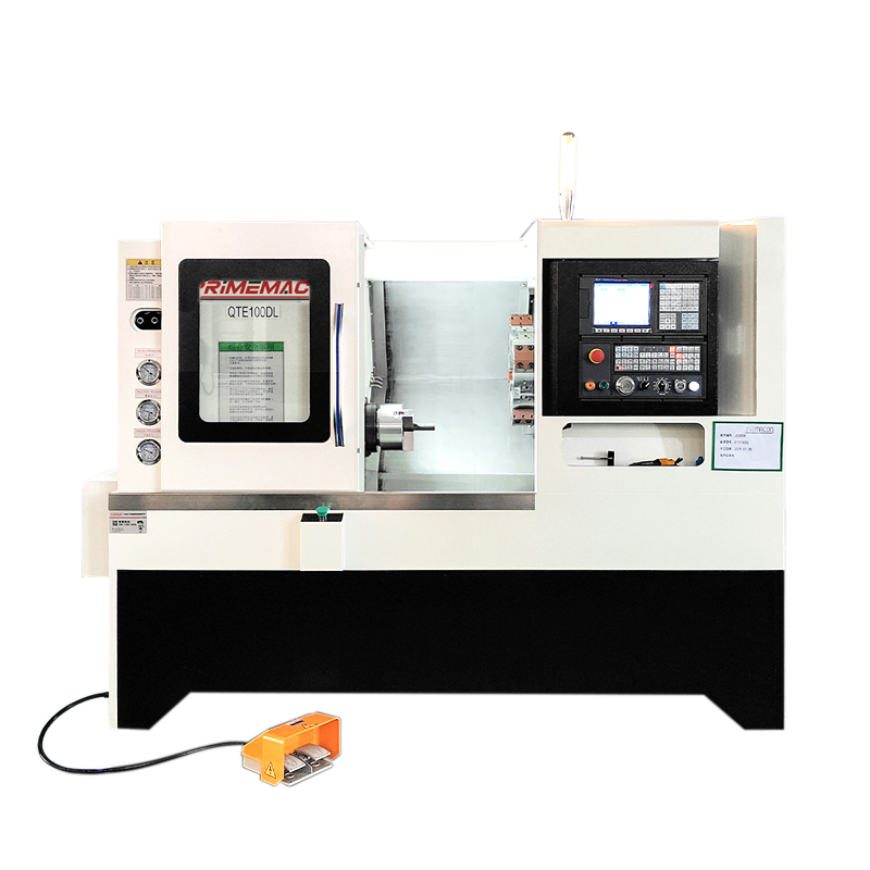
Power monitoring tracks the electrical current drawn by the main spindle and servo axes during a cut. As an insert dulls, the friction and cutting resistance increase. The machine's motors must draw more amperage to maintain the programmed feed rate and spindle speed. By establishing a baseline load for a new tool, the software can track the gradual increase in amperage as the tool wears down.
This technology is highly effective for detecting wear during heavy turning, facing, and large-diameter boring operations where the cutting forces are substantial. However, power monitoring struggles with small-diameter tools. The cutting force generated by a 2mm drill or a small grooving tool is negligible compared to the baseline friction and inertia of the machine's drivetrain. The wear signature of these micro-tools remains invisible to standard load meters.
Driven tools mounted on the turret—used for off-center drilling, tapping, and milling—require specialized monitoring approaches. A Servo Turret CNC Lathe utilizes independent servo motors to drive these tools. Advanced monitoring systems must isolate the specific load signature of the live tool motor from the main spindle and the axis drives.
By monitoring the live tooling drive directly, the system detects micro-wear on small end mills and drills that would otherwise be masked by the heavy mass of the turret assembly. If a 1/4-inch end mill starts packing with aluminum chips, the live tool servo will spike in load. The monitoring system catches this localized spike and halts the feed before the end mill snaps inside the workpiece.
Acoustic Emission (AE) sensors detect high-frequency stress waves generated by the deformation and fracturing of materials at the cutting zone. Unlike power monitoring, AE is incredibly sensitive. It detects micro-fractures, insert chipping, and tool breakage in real-time, regardless of the tool's physical size. When a carbide edge chips, it releases a distinct high-frequency acoustic burst that the sensor captures instantly.
Vibration analysis utilizes accelerometers to monitor lower-frequency mechanical oscillations. This method excels at detecting chatter during long-overhang boring operations. If a boring bar starts resonating inside a deep cylinder, the accelerometer detects the harmonic shift. The system can then alert the control to adjust the spindle speed slightly to break the chatter frequency, saving the surface finish.
Non-contact tool presetters and laser measurement systems provide physical dimensional verification between machining cycles. These systems project a laser beam across the tool tip to measure exact length and diameter. The machine indexes the tool through the beam, and the system instantly detects edge wear or a snapped tool based on the broken light beam.
While laser verification provides absolute certainty regarding the tool's physical state, it introduces a trade-off. Physical measurement routines require the turret to index, position the tool in the laser path, run the measurement macro, and return to the cut. This increases overall cycle times. Shops typically utilize this method for critical features, such as verifying a finishing tool right before a tight-tolerance bearing journal pass.
Monitoring Technology | Primary Machining Application | Operational Strengths | System Limitations |
|---|---|---|---|
Spindle Power Monitoring | Heavy roughing, large boring, facing | Cost-effective, utilizes existing machine servo data without extra sensors | Ineffective for micro-tools, light finishing, and small drills |
Acoustic Emission (AE) | Micro-machining, finishing, breakage detection | Highly sensitive to chipping, micro-wear, and sudden tool failure | Complex mechanical integration, sensitive to background shop noise |
Vibration Analysis | Deep boring, interrupted cuts, chatter detection | Identifies harmonic resonance and poor surface finish conditions | Requires rigid sensor mounting, less effective for gradual flank wear |
Laser Measurement | Dimensional verification between cycles | Absolute physical certainty of tool state and exact offset values | Increases cycle time, susceptible to coolant and chip interference |
Mounting wired sensors on a fast-indexing servo turret presents severe mechanical realities. A modern 12-station turret indexing in 0.2 seconds generates massive G-forces. Any external cabling subjected to this rotation experiences extreme fatigue, tangling, and potential severing. You cannot simply run a standard wire from a rotating tool block to the machine casting.
To overcome this, integrators utilize wireless sensor nodes that transmit AE or vibration data via radio frequencies. These battery-powered nodes bolt directly to the turret face. Alternatively, slip-ring data transmission technologies can be engineered directly into the turret housing. Slip rings allow continuous, hardwired data transfer through rotating electrical contacts, moving data from the rotating tool block to the stationary machine casting without restricting movement or risking cable failure.
Monitoring hardware must interface seamlessly with common control architectures like FANUC, Siemens, or Mitsubishi. This requires high-speed data sampling rates and exceptionally low-latency communication. Interfacing with systems like FANUC FOCAS requires specific Ethernet protocols and macro variable access unlocked in the machine parameters.
If an insert shatters during a rapid feed move, the monitoring system must process the spike in acoustic emission and send a feed-hold signal to the CNC control in milliseconds. A delay of even a fraction of a second results in the broken tool plowing into the workpiece at rapid traverse speeds. The integration must bypass standard ladder logic delays and tie directly into the emergency stop or feed-hold circuits.
Modern shop floors require tool wear data to flow beyond the machine control. Evaluating a system's compatibility with MTConnect, OPC UA, and API accessibility dictates how easily you can feed real-time data into broader ERP or MES systems. Shop managers need dashboards showing which machines are consuming tools faster than expected.
Processing this data involves choosing between edge computing and cloud analytics. Edge computing processes high-frequency sensor data locally at the machine using an industrial PC. This ensures zero latency for critical machine stops. Cloud analytics push the aggregated data to remote servers, which is better suited for long-term trend analysis and predictive maintenance modeling across multiple facilities.
The cutting zone of a turning center is a hostile environment. Any sensor, cable, or transmitter mounted inside the enclosure must meet strict environmental criteria. High-pressure coolant systems running at 1,000 PSI will destroy standard sensors, forcing synthetic fluids past cheap rubber seals and shorting out circuit boards.
IP67 or IP68 rated enclosures are mandatory. Cables must feature polyurethane or Teflon jackets to resist chemical degradation from cutting fluids. Furthermore, the hardware must withstand the physical impact of hot, flying chips and the continuous, heavy vibration generated by interrupted cuts and high-speed spindle rotation. Sensor faces must be flush-mounted or protected by armored shields to prevent chip accumulation.
Advanced monitoring systems do more than just trigger alarms; they actively manage the machining process. Software capable of automated tool offset compensation detects gradual wear trends and automatically writes macro variables directly to the CNC control. As the cutting edge wears down, the tool physically shortens.
The system calculates this wear based on the load increase and sends a command (such as a G10 L50 block in FANUC) to adjust the tool offset by microns. This maintains strict dimensional accuracy on the workpiece. This closed-loop process eliminates the need for operators to manually measure parts, open the machine door, and punch offset adjustments into the control panel. The machine stays in cycle, and the parts stay in tolerance.
To maintain continuous production, monitoring software must interact with the lathe's internal tool management system. When the software detects that a primary roughing tool has reached its maximum wear limit, it initiates a specific sequence to swap the tool without stopping production.
The software detects a sustained load spike exceeding the established wear limit for the active tool.
The system flags the current tool station as expired in the CNC control's offset registry.
The machine safely retracts the worn tool from the cut at the end of the current toolpath.
The turret indexes to a redundant (sister) tool pre-loaded in another station.
The cycle resumes using the fresh tool without requiring any operator intervention.
This capability keeps the machine running unattended for hours, seamlessly bypassing worn tools. You can load three identical roughing tools into the turret before leaving for the night, knowing the machine will cycle through them as they wear out.
Material hardness is rarely uniform. Forgings and castings often contain hard spots, scale, or inclusions. When a tool encounters a hard spot, the cutting load spikes instantly, often leading to premature edge failure or catastrophic breakage. Standard CNC programs push the tool through the material at a constant feed rate, regardless of the resistance.
Software featuring adaptive feedrate control monitors the spindle load in real-time. When it detects an abnormal load increase indicating a hard spot, it dynamically reduces the axis feedrate. This lowers the chip load and protects the tool edge. Once the tool clears the hard spot and the load drops, the software ramps the feedrate back to the programmed optimal speed. This extends tool lifespan and prevents breakage during inconsistent material batches.
A monitoring system that constantly stops the machine for false alarms will quickly be bypassed by frustrated operators. If the machine stops every time the coolant pump surges or the material gets slightly harder, production grinds to a halt. Modern systems utilize dynamic envelope learning and machine learning algorithms to differentiate between normal process variations and actual tool failure.
The software learns the acceptable load variations caused by thermal expansion, slight material batch inconsistencies, and fluid dynamics. It builds a dynamic baseline envelope around the standard cutting load. The system only triggers an alarm when a signature clearly breaks outside this envelope, indicating a chipped insert or severe wear. This intelligence keeps the machine running through minor fluctuations while still catching genuine failures.
The primary risk during implementation is the extensive teaching required for the system. If operators must run multiple baseline cycles for every new part program to establish alarm limits, the time savings are negated. Job shops running batches of 50 parts cannot afford to spend 5 parts teaching the monitoring system how to behave.
To mitigate this, prioritize systems equipped with intuitive, auto-tuning software that can establish baselines after a single cycle. Focus the initial deployment on long-running, high-value production jobs where the ROI of unattended machining is highest. Once the operators understand how the software builds its baselines on the easy jobs, they can apply those principles to the shorter, more complex runs.
Operators are often skeptical of automated monitoring, viewing it as a hindrance or a "big brother" tool rather than a helpful asset. If the system is configured with overly sensitive alarm thresholds out of the box, it will frequently halt production. Operators will view it as a nuisance and find ways to disable it entirely.
Mitigate this risk through a phased rollout. Start the system in a monitoring-only mode. Allow it to gather data and log potential alarms without actually stopping the machine or altering feed rates. Review this data with the operators to tune the thresholds accurately. Once the operators see that the system accurately predicts tool failure without causing false stops, they will trust it enough to enable automatic machine stops.
Sensor degradation over time is a silent failure point. Coolant ingress, cable fatigue inside the energy chains, or chip buildup on a laser lens will lead to inaccurate readings or missed tool breakages. If the system goes blind, the machine is unprotected.
Establish a standardized preventative maintenance schedule specific to the monitoring hardware. Do not treat the sensors as install-and-forget devices.
Maintenance Task | Frequency | Action Required |
|---|---|---|
Sensor Face Cleaning | Weekly | Wipe down AE and vibration sensors to remove fine chip dust and coolant residue. |
Cable Integrity Check | Monthly | Inspect polyurethane jackets for swelling, cracking, or pinch points near the turret housing. |
Laser Lens Inspection | Bi-Weekly | Clean transmitter and receiver lenses with approved optical solvent to ensure beam clarity. |
Baseline Calibration Verification | Quarterly | Run a known standard tool through a test cut to verify the load meter readings match historical data. |
Tool wear monitoring is a highly integrated process control strategy that pays massive dividends in high-volume or high-value turning applications. Transitioning from reactive tool changes to predictive, data-driven machining eliminates the compounding costs of scrapped parts and machine damage. When shortlisting technologies, match the sensor architecture to the application. Select power-based systems for heavy roughing on older machines, and deploy acoustic emission or vibration systems for precision applications on modern servo-driven equipment.
To successfully integrate these systems into your turning operations, follow these immediate next steps:
Audit your current scrap logs to identify the specific machining operations and part numbers causing the highest tool failure rates.
Install a basic power monitoring system on a single bottleneck machine to establish baseline load data and prove the concept to your operators.
Partner with an integration specialist to map out the macro variable requirements and ladder logic access for your specific CNC control make and model.
Run a 30-day pilot program in monitoring-only mode to tune alarm thresholds before enabling automatic machine stops or sister tool changes.
A: Yes. Older machines typically use external power monitoring sensors installed directly in the electrical cabinet to track spindle and axis loads. You clamp inductive sensors around the power leads. However, integrating advanced features like automated offset compensation might face limitations depending on the processing speed and macro variable accessibility of the legacy CNC control.
A: The ROI timeline generally ranges from 6 to 12 months. This is achieved through a direct reduction in scrapped parts, extended consumable tool life, and the ability to safely run unattended overnight shifts. Running lights-out drastically increases overall machine utilization and output without adding labor costs.
A: Wiring on a rotating turret is managed using specialized slip-ring assemblies built into the turret hub, allowing continuous electrical contact during rapid rotation. Alternatively, modern setups utilize battery-powered wireless sensor nodes mounted directly on the tool block that transmit data via radio frequency to a stationary receiver.
A: Yes. Advanced systems monitor the independent servo motors driving the live tools. By isolating the electrical current or acoustic signature of the live tool drive from the main spindle, the software accurately detects wear and breakage on small end mills, taps, and drills mounted in the turret.
A: Breakage detection looks for sudden, massive spikes or drops in cutting force, instantly stopping the machine to prevent a crash. Tool wear monitoring tracks gradual, incremental increases in cutting load or acoustic emission over time, predicting when a tool will fail so it can be replaced proactively before it breaks.
A: It can slightly increase cycle time on a specific part if the tool encounters hard spots and slows down. However, by preventing tool breakage and eliminating the downtime required to extract broken tools or rework scrapped parts, the overall production throughput and efficiency for the entire batch significantly increase.
A: Systems use dynamic envelope learning. Material hardness variations usually cause temporary, localized spikes in cutting load that drop back to normal once the hard spot is cleared. Tool wear causes a permanent, gradual upward trend in the baseline cutting load across the entire toolpath, which the software algorithms identify and flag.


