

Views: 0 Author: Site Editor Publish Time: 2026-09-23 Origin: Site


In high-mix, tight-tolerance manufacturing, the precision of a machined component is strictly limited by the repeatability of the machine's tool-changing mechanism. While standard engine lathes rely on manual tool changes, automated systems revolutionized high-production turning. However, modern complex geometries demand more than just automated tool changes. They require micron-level indexing precision to maintain tight tolerances across multiple operations.
Micro-misalignments during tool indexing compound rapidly. These small deviations lead to tolerance stacking, increased scrap rates on complex geometries, and compromised surface finishes. When a tool does not return to its exact programmed center height, the resulting cutting forces shift, causing chatter and dimensional inaccuracies. Mitigating these errors requires a technical evaluation of how different indexing systems handle rigidity, thermal stability, and tool positioning under heavy cutting loads. Manufacturers must understand the mechanics of traditional cam-driven setups compared to advanced servo-driven turrets to optimize their machining processes.
Indexing Repeatability Dictates Yield: The locking mechanism of a turret directly influences tool center height and runout, which are critical for holding micron-level tolerances.
Servo Control Enables Optimization: Transitioning to a servo-driven indexing system allows for programmable acceleration and deceleration, reducing mechanical shock, preserving coupling accuracy over time, and enabling safe visual clearance checks.
Live Tooling Amplifies Rigidity Requirements: Utilizing driven tools on a power turret introduces radial and axial forces that require high-clamping-force curvic or Hirth couplings to prevent deflection.
Clearance Management is Critical: Complex part geometries demand precise programming of safe indexing positions (e.g., G30 vs. G53) to prevent catastrophic tool interference and machine downtime.
Understanding turret performance requires differentiating between indexing accuracy and repeatability. Indexing accuracy refers to the system's ability to reach an absolute programmed rotational position. Repeatability measures the system's ability to return to that exact same position over multiple cycles. In high-precision turning, repeatability often outweighs absolute accuracy. If a tool consistently returns to the same spot, operators can offset the wear or deviation in the CNC control. If repeatability fluctuates, offsets become useless.
Angular deviation at the turret coupling translates directly to amplified linear deviation at the cutting tool tip. This phenomenon is known as the sine error effect. A microscopic angular misalignment at the coupling center multiplies as the distance from the center increases. For example, an angular error of just 0.001 degrees at the coupling will cause a significant shift at the tip of a standard turning tool. This shift alters the tool center height, changing the cutting geometry and inducing chatter or dimensional taper on the workpiece. When you are turning bearing journals to a total tolerance of 0.0005 inches, even a fraction of a degree in indexing error will scrap the part.
Tool overhang exacerbates indexing inaccuracies. Extended boring bars, long drills, and custom tooling setups act as lever arms. These extended lengths magnify minor indexing misalignments at the coupling. When a boring bar extends six inches from the turret face, even a sub-micron angular deviation at the base results in a measurable radial error at the cutting edge. This error compromises deep-hole tolerances and surface finishes.
Gravity and heavy tool loads introduce another physical challenge known as turret droop. As operators load the turret with heavy boring bars and live tool holders, the sheer mass pulls the turret housing downward. The indexing clamping mechanism must counteract this force during the locking phase. A robust clamping system lifts and seats the turret perfectly on center, eliminating the droop. If the clamping force is insufficient or the coupling teeth are worn, the turret will lock in a slightly drooped position, permanently altering the tool center height.
Several factors accelerate turret droop and indexing wear on the shop floor:
Mounting excessively heavy boring bars without proper counterbalancing on the opposite side of the turret.
Running interrupted cuts that send severe shockwaves through the tool block and into the coupling teeth.
Failing to maintain proper hydraulic pressure in the clamping circuit, leading to weak seating force.
Ignoring chip buildup behind the turret face, which can wedge into the coupling during a tool change.
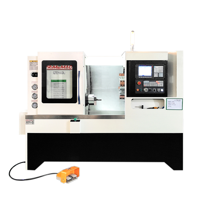
Legacy indexing systems rely heavily on cam-driven and hydraulically clamped mechanisms. Cam-driven turrets use a mechanical barrel cam to translate rotational motion into the lifting, indexing, and seating phases. Hydraulic turrets utilize fluid pressure to unclamp the coupling, a hydraulic motor or Geneva mechanism to rotate the turret, and fluid pressure to clamp it back together. These systems formed the baseline of automated turning for decades.
These legacy systems present significant limitations for modern tight-tolerance work. Cam-driven systems operate at fixed indexing speeds and suffer from higher mechanical wear over time. Hydraulic systems are highly susceptible to fluid temperature fluctuations. As the machine runs and the hydraulic oil heats up, its viscosity changes. This thermal shift can cause fluctuations in the clamping force, leading to inconsistent seating and degraded indexing repeatability during long production runs. You might find that a machine holds tolerance perfectly in the morning but starts cutting tapers by the afternoon shift simply because the hydraulic oil thinned out.
Traditional camshaft-automated sliding and indexing mechanisms fall short in modern manufacturing environments. These systems rely on physical cams cut to specific profiles to dictate tool movement and indexing timing. Changing a part setup requires physically swapping or adjusting these cams. This process is labor-intensive and highly inflexible.
The lack of programmable flexibility makes legacy camshaft systems ineffective for producing complex, multi-axis geometries. Modern components often require dynamic tool path adjustments, variable indexing speeds, and the ability to skip tool stations rapidly. Cam-driven automation cannot adapt to these dynamic programming requirements without extensive mechanical intervention, rendering them obsolete for high-mix, low-volume production where changeovers happen daily.
Modern manufacturing relies heavily on the Servo Turret CNC Lathe to achieve micron-level accuracy. These machines utilize AC servo motors for rotational positioning. The servo motor operates independently of the clamping mechanism. When a tool change is commanded, the turret unclamps, the servo motor rotates the top plate to the exact position using high-resolution encoder feedback, and the mechanism clamps back down.
This architecture provides massive production benefits. Operators gain complete control over indexing speed. The servo control allows for bidirectional tool selection, automatically calculating the shortest path to the next tool station. Servo systems utilize programmable acceleration and deceleration curves. This eliminates the violent mechanical shock often seen in hydraulic systems during seating, preserving the integrity of the coupling teeth over millions of cycles.
Setup advantages are equally significant. Modern servo controls allow operators to reduce rapid traverse rates to slow down the indexing rotation. This capability is vital during first-article prove-outs. Operators can visually inspect clearance between long tools, the chuck, and the tailstock as the turret rotates slowly, preventing catastrophic collisions that would otherwise destroy the machine's alignment.
A Power Turret CNC Lathe integrates milling capabilities directly into the turning center. These machines utilize specialized turret interfaces, primarily Base Mounted Turret (BMT) or Verein Deutscher Ingenieure (VDI). BMT interfaces bolt the tool holder directly to the face of the turret using four screws and alignment keys, offering superior rigidity. VDI interfaces use a single serrated shaft and wedge mechanism, allowing for faster tool changes but sacrificing some heavy-milling rigidity.
Comparison of BMT and VDI Turret Interfaces | ||
Feature | BMT (Base Mounted Turret) | VDI (Verein Deutscher Ingenieure) |
|---|---|---|
Mounting Method | 4 bolts with alignment keys | Single serrated shaft with wedge |
Rigidity for Heavy Milling | Excellent | Moderate |
Tool Change Speed (Manual) | Slower (requires tightening 4 bolts) | Faster (single locking screw) |
Center Height Accuracy | Highly repeatable due to keyways | Prone to slight rotational shift |
Best Application | Heavy interrupted cuts, tough alloys | Light milling, high-mix quick setups |
Integrating drive motors for live tooling significantly increases the overall mass of the turret. This added weight necessitates robust, high-pressure clamping mechanisms. When performing off-center milling operations, the live tool generates heavy radial and axial cutting forces. The turret coupling must resist these forces to maintain indexing accuracy. If the coupling deflects under load, the milled features will be out of tolerance.
Indexing live tooling requires strict safety and clearance protocols. Driven tools, right-angle milling heads, and inserted drill bodies drastically alter the interference envelope of the turret. The added tool length and milling cutter diameters increase the risk of collision with sheet metal, way covers, or the workpiece during rotation. Programmers must account for this expanded envelope when establishing safe indexing positions.
The heart of any turret indexing system is its coupling mechanism. The two most prominent designs are curvic couplings and Hirth gear couplings. Both utilize interlocking teeth to secure the turret top plate to the machine base, but their geometries differ significantly.
Curvic couplings feature curved, convex, and concave teeth machined onto the face of the coupling rings. This curved geometry provides exceptional self-centering capabilities. As the coupling clamps together, the curved teeth naturally guide the top plate into perfect alignment. Hirth couplings utilize straight, V-shaped teeth radiating from the center of the ring. While also highly accurate, Hirth couplings generally offer slightly less self-centering action compared to curvic designs.
Comparison of Turret Coupling Technologies | ||
Feature | Curvic Coupling | Hirth Coupling |
|---|---|---|
Tooth Geometry | Curved (Convex/Concave) | Straight (V-Shaped) |
Self-Centering Capability | Exceptional | High |
Contact Surface Area | Very High | Moderate to High |
Vibration Dampening | Superior | Adequate |
Manufacturing Complexity | Higher | Lower |
Coupling surface area and clamping force directly correlate to vibration dampening. A larger coupling diameter with more tooth contact area absorbs cutting vibrations more effectively. This dampening translates directly to improved surface finish quality on the workpiece and extended tool life for inserts. When you push a heavy roughing tool through Inconel, the coupling absorbs the brunt of that force. A weak coupling allows micro-vibrations that will chip your carbide inserts prematurely.
Continuous machining operations generate significant heat. In power turrets, the live tool drive motors generate internal heat directly inside the turret casting. This localized heat causes thermal expansion. As the metal expands, the turret center height can drift, pushing tight-tolerance dimensions out of specification.
Machine tool builders implement several countermeasures to combat thermal deformation. Coolant-through-turret systems help dissipate heat by circulating cold cutting fluid through the casting. Advanced CNC controls utilize thermal compensation algorithms. These algorithms use strategically placed thermistors to monitor casting temperatures and automatically apply micro-offsets to the X and Y axes to counteract thermal growth. Symmetrical turret casting designs ensure that when the metal does expand, it expands evenly, minimizing angular distortion.
Maintaining accuracy and safety during indexing requires precise programming strategies. Programmers must establish safe locations for the turret to rotate without causing interference. Modern controls rely on specific G-codes to manage these positions.
G53 commands the machine to move to a specific coordinate based on the machine coordinate system. This system is fixed and unchangeable by the operator. Programming a tool change at a specific G53 location ensures the turret always indexes in the exact same physical space, regardless of active work offsets. G30 commands the machine to move to a secondary reference point return. This position is defined in the machine parameters. While effective, G30 relies on parameter settings that can be altered by an operator trying to shave seconds off a cycle time. G53 is generally considered the safer, more rigid programming method for establishing repeatable indexing locations that clear complex part geometries, steady rests, and tailstocks.
Evaluating indexing technology requires balancing initial capital expenditure against long-term cycle time reductions. High-speed servo indexing systems command a higher upfront cost due to the inclusion of AC servo motors, high-resolution encoders, and advanced drive amplifiers. However, these systems drastically reduce non-cut time.
A standard hydraulic turret might take 1.5 seconds to unclamp, index one station, and reclamp. A modern servo turret can accomplish the same index in 0.2 seconds. While a 1.3-second savings seems minimal, it compounds rapidly. In a high-volume production environment running parts with ten tool changes per cycle, that saves 13 seconds per part. Over a production run of 50,000 components, this non-cut time reduction frees up hundreds of hours of machine capacity. Manufacturers must assess their volume thresholds to determine where the speed of a servo turret justifies the initial investment over a standard hydraulic system.
Different indexing systems present distinct maintenance complexities that impact long-term operational expenses. Cam-driven and hydraulic systems require rigorous mechanical maintenance. Operators must monitor hydraulic fluid levels, replace degraded filters, and ensure mechanical cams receive adequate lubrication. Mechanical wear on locking pins and cam tracks eventually requires costly physical rebuilds.
Servo-driven systems shift the maintenance focus from mechanical wear to electronic calibration. Maintenance teams must manage encoder batteries, tune servo drive parameters, and ensure cables remain free of coolant ingress. While mechanical wear is lower, electronic components require specialized diagnostic skills. The cost of replacing damaged curvic couplings due to severe indexing collisions is substantial. Investing in preventative collision-avoidance software often offsets these expenses by stopping the machine before a catastrophic crash destroys the coupling.
Machining complex, multi-axis parts introduces severe tool clearance risks. When using a Turret Lathe, adjacent tools can easily interfere with the workpiece or machine components. For example, a long boring bar mounted next to a short turning tool might strike the tailstock quill while the turning tool is engaged in the cut. Similarly, long drills can hit the chuck jaws during an index if the safe position is programmed too close to the spindle.
Mitigating this risk requires utilizing advanced CAM simulation software. Programmers must build accurate digital twins of the specific lathe, including the exact turret geometry, chuck jaws, and sheet metal enclosures. Running a full kinematic simulation verifies clearance paths for all tools before the G-code is post-processed and sent to the shop floor. This digital verification prevents physical crashes and protects the indexing coupling from blunt force trauma.
Advanced indexing controls introduce the risk of operator error. Operators accustomed to legacy machines might manually intervene during a tool change sequence or override indexing speeds inappropriately. Pressing emergency stop in the middle of a servo index can leave the turret unclamped and out of position, requiring a complex recovery procedure.
Mitigation relies on strict standardization and training. Engineering teams should standardize setup sheets to clearly define safe indexing zones and required tool stick-out lengths. CNC controls should be parameterized to lock out rapid override dials during the indexing macro, ensuring the turret always rotates at the programmed safe speed. Operators must receive specific training on safe recovery procedures following an emergency stop, ensuring they can realign and clamp the turret without causing mechanical damage.
Audit current scrap rates specifically related to tool center height deviations and taper errors to identify failing indexing couplings.
Request a detailed time-study from machine tool builders comparing indexing times between hydraulic and servo turrets for your specific high-volume parts.
Require a test cut of your most complex, heavy-milling part during machine evaluation to verify coupling rigidity under actual cutting loads.
Implement standardized CAM simulation protocols to verify all turret indexing clearances before running first articles on the shop floor.
A: An engine lathe typically features a standard tool post requiring manual tool changes by the operator. A turret lathe utilizes an indexable multi-tool turret, enabling automated, high-production turning without manually resetting tools between operations.
A: A capstan lathe mounts the turret on a short slide moving on a saddle, which limits stroke length and overall rigidity. A turret lathe mounts the turret directly on the main saddle, providing the massive rigidity required for heavy cuts and complex indexing.
A: Modern servo turrets utilizing high-precision curvic couplings can achieve indexing repeatability of ±0.0001 inches or better. This precise repeatability depends heavily on the machine builder's casting quality and the specific diameter of the coupling.
A: Turrets lose alignment primarily due to mechanical collisions or crashes. Other causes include wear on the coupling teeth over millions of cycles, hydraulic pressure drops in the clamping mechanism, or debris ingress into the coupling area.
A: Live tooling adds significant mass to the turret and introduces off-axis milling forces. If the turret coupling is not sufficiently rigid, these cutting forces can cause micro-deflections that degrade indexing repeatability and part accuracy over time.
A: Use G53 to command the turret to a specific, safe machine coordinate position, or G30 for a verified secondary reference point. This ensures the tool is entirely clear of the chuck, workpiece, and tailstock before rotation begins. Reducing rapid rates during prove-out allows for visual clearance confirmation.


