

Views: 0 Author: Site Editor Publish Time: 2026-08-05 Origin: Site


In aerospace manufacturing, unmitigated runout in high-speed rotating parts leads to catastrophic vibration. You see accelerated wear and immediate part rejection when machining critical turbine shafts and compressor rotors. Flight safety depends entirely on eliminating these dynamic imbalances early in the manufacturing process.
Tooling choices and setup routines certainly play a role in part quality. However, consistent Geometric Dimensioning and Tolerancing (GD&T) compliance at the micron level begins fundamentally elsewhere. It stems directly from the inherent structural rigidity and baseline spindle accuracy of the machine tool. A perfect setup cannot fix a weak spindle.
Manufacturers often need to upgrade turning capabilities to meet strict AS9100 standards. Evaluating a CNC Lathe requires you to look far beyond glossy brochure specifications. You will learn how to properly scrutinize thermal stability, workholding integration, and tailstock performance. We will explore exactly how spindle architecture prevents deflection and eliminates tolerance stacking.
Total runout control in aerospace applications relies heavily on the spindle architecture and thermal compensation of a Precision CNC Lathe Machine.
Machining long, high-L/D-ratio rotating components dictates the need for a CNC Lathe Machine with Tailstock to prevent deflection and tolerance stacking.
Procurement evaluation must require vendor-supplied test cuts, verifiable CPK (Process Capability Index) data, and CMM (Coordinate Measuring Machine) validation to prove runout guarantees.
Operational realities—such as chuck jaw boring, tool pressure, and material stress relief—must align with the machine’s baseline accuracy to eliminate scrap.
Understanding the strict definitions within GD&T separates acceptable parts from scrap. We must clearly differentiate between Circular Runout (2D) and Total Runout (3D). Circular runout measures variations across a single cross-sectional slice of a cylinder. Total runout evaluates the entire cylindrical surface simultaneously along the axis. Aerospace rotating parts demand strict Total Indicator Reading (TIR) compliance. You must control the entire surface geometry to prevent destructive vibration at high operating RPMs.
Tolerance stacking from uncontrolled runout leads directly to dynamic imbalance. Mass offset from the true center of rotation generates severe centrifugal forces. These forces scale aggressively as rotational speeds increase. This dynamic imbalance ruins high-value alloys like Inconel and Titanium. Scrapping these exotic materials instantly disrupts production schedules. More importantly, flying with compromised rotating components threatens absolute flight safety.
You need highly stringent success criteria to validate aerospace components. Final part TIR specifications often demand tolerances tighter than 0.005mm (0.0002"). Hitting this mark directly off the machine saves significant time. It prevents you from relying on expensive and time-consuming secondary grinding operations. A rigid machine platform achieves this baseline capability naturally.
Inherent machine design choices directly impact long-term runout control. Integrating a Precision CNC Lathe Machine is essential for aerospace manufacturing. You cannot rely on software alone to fix poor mechanical foundations. True accuracy begins at the spindle.
Evaluating spindle design and bearings requires deep technical scrutiny. Ultra-precision angular contact bearings form the heart of a capable spindle. You must differentiate between dynamic and static runout specifications. A machine might show zero static runout during a manual dial indicator test. However, under high RPM, centrifugal forces reveal dynamic runout. Robust vibration dampening capabilities inside the spindle housing neutralize these dynamic shifts.
Thermal stability plays a massive role in maintaining concentricity. Long aerospace turning cycles generate intense friction and heat. This heat causes the spindle casting to grow linearly. Thermal displacement compensation systems monitor these temperature gradients constantly. They dynamically adjust axis positions to keep the tool perfectly aligned with the spindle centerline.
Structural rigidity determines how the machine handles aggressive cutting forces. We constantly compare Box Way versus Linear Guide designs. Linear guides offer rapid traverse speeds. Box ways offer massive vibration dampening through broad surface contact. When you hard-turn aerospace alloys, high tool pressure easily induces deflection. This deflection creates artificial runout. Box way machines resist this pressure better during heavy roughing.
Evaluate bearing arrangements and preload specifications carefully.
Demand static TIR measurements directly at the spindle nose.
Require dynamic TIR validation at the maximum operating RPM.
Verify the presence of integrated cooling jackets for thermal regulation.
Check the casting geometry for optimal vibration absorption.
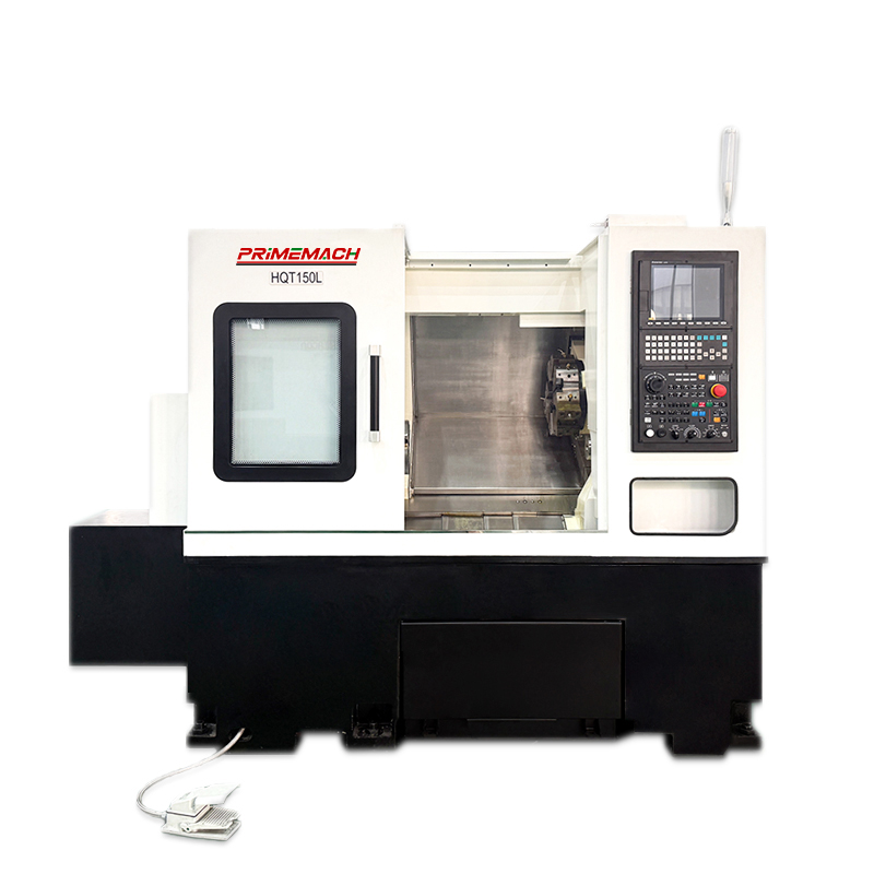
Machining geometry dictates your equipment requirements. Rotating aerospace shafts frequently exceed a Length-to-Diameter (L/D) ratio of 3:1. You simply cannot machine them accurately on standard chucking lathes. The unsupported end of the part will bow away from the cutting tool. You absolutely need a CNC Lathe Machine with Tailstock to anchor the workpiece securely.
Programmable tailstocks provide essential stability for slender shafts. You can choose between hydraulic and servo-driven tailstock systems. Servo-driven options provide precise, highly repeatable thrust control. You must support the workpiece without applying excess axial pressure. Too much pressure bows the shaft artificially. Too little pressure allows chatter and harmonic vibration.
Live center selection is equally critical to runout mitigation. You must match the live center runout specifications to the main spindle. A substandard center transfers its own runout directly into the part geometry. High-precision bearings inside the live center ensure the tailstock end rotates perfectly true.
You face a common decision between specifying a sub-spindle or a tailstock. The decision impacts your process routing and structural rigidity.
Feature Focus | Tailstock Application | Sub-Spindle Application |
|---|---|---|
Primary Advantage | Maximum rigidity for long shafts | Multi-tasking and automated part handoff |
L/D Ratio Limit | Handles ratios > 3:1 easily | Best for ratios < 3:1 (chucking parts) |
Thrust Control | Programmable servo thrust | Dependent on chuck gripping force |
Runout Risk | Live center quality dependency | Spindle synchronization errors |
Aerospace Use Case | Turbine shafts, landing gear struts | Valves, flanges, short bearing rings |
A flawless spindle can still produce severe runout. Compromised workholding is usually the primary culprit. These implementation risks destroy the inherent accuracy of your machine tool. You must treat the chuck and the cutting tool as direct extensions of the spindle.
Chuck and collet selection drives final part concentricity. Standard 3-jaw chucks often crush thin-walled aerospace rings. They cause significant gripping distortion that mimics runout upon release. You should transition to high-precision diaphragm chucks. Precision collet systems also help eliminate localized pressure points on delicate components.
Soft jaw preparation demands strict standard operating procedures. You cannot simply bore jaws loosely. You must bore soft jaws under active clamping pressure. This procedure uses a precision boring ring. It perfectly matches the final jaw geometry to the actual spindle rotation under load.
Install the uncut soft jaws onto the master chuck.
Clamp the jaws down firmly onto a precision boring ring.
Machine the gripping faces to the exact diameter of your workpiece.
Remove the ring and clean all surfaces to eliminate micro-chips.
Clamp the actual aerospace part and verify initial runout with a dial indicator.
Cutting tool strategies also influence apparent runout. Select positive insert geometries whenever possible. They minimize radial cutting forces during the pass. High radial forces push the part off-center, creating a tapered or eccentric profile. Manage tool wear diligently. Dull tools increase radial push-off exponentially.
Procurement teams must adopt an evidence-oriented evaluation strategy. You must move far beyond standard marketing claims. Requesting verifiable data protects your investment. You need absolute proof before approving any capital expenditure.
The Acceptance Test Procedure (ATP) forms your strongest safeguard. Mandate a runoff test on a representative aerospace part. Supply your own specified material, such as Ti-6Al-4V or Inconel 718. The vendor must machine this part holding your exact TIR tolerances. This proves the machine's true cutting capability under real-world conditions.
Capability studies reveal the consistency of the machine tool. Request Cp and Cpk data directly from the runoff test. You must prove the machine holds runout tolerances across a continuous batch. A single "golden part" proves nothing about thermal stability or long-term repeatability. You want a Cpk value greater than 1.33 for critical aerospace dimensions.
Post-sale support guarantees long-term success. Evaluate the vendor's service level agreement (SLA) for geometry realignment. Ask about their schedule for laser calibration and ball-bar testing. Machine foundations settle over time. Spindles take accidental impacts. Routine calibration maintains original runout capabilities over the machine's entire lifecycle.
Runout control in aerospace manufacturing represents a complex, systemic challenge. You solve it by pairing rigorous operational procedures with a highly rigid, thermally stable machine platform. Precision starts at the spindle and extends through the tailstock, workholding, and tooling.
Treat baseline machine rigidity as the foundation for micron-level GD&T compliance.
Control thermal displacement actively to maintain concentricity during long cycles.
Support high-L/D-ratio parts firmly to eliminate tool pressure deflection.
Bore soft jaws under pressure to prevent gripping distortion.
Demand continuous capability data (Cpk) rather than single-part runoff results.
Advise your engineering and procurement teams to clearly define maximum TIR requirements immediately. Calculate your expected L/D ratios before you approach equipment suppliers. Use this data to request vendor application engineering reviews and highly customized test cuts.
A: Concentricity strictly controls the derived median points of a cylindrical feature relative to a datum axis. Runout controls the actual surface variations during full rotation. Runout is much easier to measure physically on the shop floor. It remains the more critical metric for controlling dynamic vibration in high-speed aerospace components.
A: Prolonged cutting generates immense heat inside the spindle bearings and casting. This heat shifts the spindle centerline relative to the cutting tool and tailstock. This misalignment introduces eccentric errors along the part. Mitigating this requires active software thermal compensation or dedicated liquid chiller systems.
A: Yes. Dull cutting inserts drastically increase radial push-off forces. This pushes the workpiece away from the tool centerline during the cut. The resulting part deflection creates geometric errors that perfectly mimic runout on CMM reports. You must distinguish between inherent machine capability and basic consumable management.


