

Views: 0 Author: Site Editor Publish Time: 2026-10-20 Origin: Site


Upgrading to a live tooling CNC lathe transitions a shop from traditional turning to one-in-done manufacturing. This leap unlocks massive productivity gains, but the choice of axis configuration heavily impacts ROI. Buyers often struggle to determine if standard C-axis interpolation is sufficient for their part families. Alternatively, they wonder if the higher capital expenditure of a true Y-axis is necessary to eliminate secondary milling operations. Making the wrong choice leads to frustrating bottlenecks or wasted budget.
This article provides a technical and commercial framework for evaluating C-axis vs. Y-axis capabilities. We focus on geometric limits, tolerance realities, and CAM software considerations to ensure confident equipment selection. You will learn exactly how to align your machining investments with your actual shop floor needs.
C-axis uses spindle rotation and X-axis movement to simulate milling, which is cost-effective but introduces limitations with off-center geometry and surface finish.
A physical Y-axis allows the cutting tool to move perpendicular to the spindle center, enabling true off-center drilling, flat machining, and tight-tolerance keyways.
Investing in Y-axis capability reduces the need to move complex parts to a 4-axis VMC (Vertical Machining Center), drastically cutting setup times and fixture costs.
CAM software configuration and post-processor tuning (e.g., forcing Y-axis toolpaths over C-axis) are critical implementation realities that require advanced programming knowledge.
Understanding the mechanical baseline is crucial for equipment selection. Prices for standard CNC lathes differ drastically based entirely on their axis design. You must know exactly how the machine executes milling commands to justify the price tag.
In a C-axis configuration, the main spindle becomes a precisely controlled rotary axis. It works simultaneously alongside the X and Z axes. The machine relies entirely on polar coordinate interpolation to machine features on the face or outer diameter of the part.
Because there is no physical Y-axis, the machine must rotate the part while moving the tool in and out along the X-axis. This simulates flat milling. However, this approach carries a major mechanical vulnerability. When the cutting tool crosses the exact center point (X=0), the interpolation must rapidly reverse direction. This sudden physical reversal often introduces microscopic backlash. Consequently, you will frequently see interpolation marks, which negatively impact the final surface finish.
A true Y-axis introduces a completely separate, physical perpendicular axis. Builders often achieve this by adding a secondary wedge way system directly onto the turret. This design allows the live tool to move vertically above or below the spindle centerline.
With a physical Y-axis, the spindle does not need to rotate to mill a flat surface. The tool simply travels straight across the part in an orthogonal line. This direct linear movement drastically improves machine rigidity. It also enhances thermal stability compared to purely relying on rotary interpolation. The cutting forces transfer more predictably into the machine casting, yielding superior accuracy.
Axis Configuration Comparison
Feature | C-Axis (Polar Interpolation) | Y-Axis (Orthogonal Movement) |
|---|---|---|
Movement Type | Simulated (Rotary + X-axis) | Physical perpendicular axis |
Off-Center Drilling | Not possible | Fully supported |
Centerline Reversal | Requires rapid X-axis reversal | Smooth linear motion across center |
Rigidity | Moderate | High (Direct structural support) |
You must evaluate your part families carefully to determine where the premium cost of a Y-axis yields diminishing returns. A C-axis is highly effective for many common applications.
Standard C-axis machines excel at specific ideal geometries. They easily handle cross-drilling directly on the centerline. They seamlessly execute basic bolt-hole patterns on the face of a part. They are also perfect for cutting simple hex flats or wrench flats. If your daily production revolves around these basic features, polar interpolation performs brilliantly.
From a cost-efficiency perspective, a compact CNC mill-turn machine equipped with just a C-axis serves as an ideal entry point. Shops upgrading from traditional 2-axis turning will see immediate workflow improvements. You can finish parts in one setup without breaking the bank on advanced kinematics.
Of course, you must accept certain compromises. Surface finishes on flats might show slight interpolation witness marks. However, this is often entirely acceptable for non-critical mating surfaces or standard hardware components. If the flat only exists for a wrench to grip, perfection is rarely necessary.
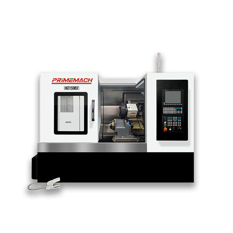
Justifying the higher capital expenditure of a Y-axis requires looking closely at expanded capabilities. This investment directly reduces scrap rates and opens doors to more complex, higher-paying contracts.
Off-center features absolutely demand a Y-axis. When a cross-drilled hole does not intersect the part's centerline, a C-axis simply cannot reach it. Furthermore, machining deep, straight-walled keyways becomes problematic without a Y-axis. Rotary interpolation often introduces a slight taper to the keyway walls. A physical Y-axis mills these slots perfectly straight every single time.
Eliminating C-axis interpolation also removes X-axis reversal errors completely. This mechanical advantage results in superior surface finishes on flat surfaces. You gain much tighter dimensional control across the entire part. When machining aerospace-grade mating surfaces, this level of precision is mandatory.
Finally, a physical Y-axis extends your tool life significantly. Maintaining a constant chip load is vital for carbide cutters. Linear Y-axis movement allows for consistent feed rates. In contrast, C-axis interpolation requires variable radial speeds, which fluctuate the chip load. Stable orthogonal milling preserves your expensive live tooling cutters for much longer.
Multi-axis turning fundamentally shifts how shops approach workflow efficiency. It forces managers to compare new mill-turn configurations against traditional multi-machine setups.
Many shop owners debate buying a Y-axis lathe versus keeping a cheaper 2-axis lathe. They consider moving turned parts to a 4-axis Vertical Machining Center (VMC) for the milling operations. This traditional approach seems cheaper initially, but it hides massive inefficiencies.
You must factor in ongoing labor costs. Every time an operator handles a part to move it between machines, you lose money. Multi-machine setups also bloat your work-in-progress (WIP) inventory. Furthermore, moving parts between fixtures introduces tolerance stack-up errors. A Y-axis lathe eliminates these secondary setups, guaranteeing better concentricity and drastically reducing operator handling time.
To maximize efficiency, many shops eventually scale up to a twin-spindle CNC mill-turn machine. Combining a true Y-axis with a sub-spindle enables complete "done-in-one" machining. The machine can turn, mill, and hand off the part automatically to finish the back side.
While the initial cost is undeniably high, the long-term benefits are staggering. You unlock the potential for true unattended or lights-out manufacturing.
Reduced Setup Times: Operators setup one machine instead of two.
Better Part Accuracy: Automated handoffs maintain absolute alignment between operations.
Labor Optimization: One operator can manage multiple twin-spindle machines simultaneously.
Faster Throughput: Raw bar stock goes in, and a completely finished part comes out.
Upgrading your hardware is only half the battle. You must address the hidden costs of adoption. Software integration and operator training present real implementation realities.
Transitioning from standard turning to Y-axis toolpaths requires a serious leap in CAM software mastery. Software packages like Mastercam or Esprit handle these operations beautifully, but only if the programmer understands the kinematics. Generating efficient Y-axis toolpaths requires deeper technical knowledge than basic 2-axis lathe programming.
Post-processor challenges are extremely common roadblocks. You must properly configure the post-processor to force the machine to use the Y-axis. Often, generic posts default to C-axis interpolation for certain features. Correcting this requires specific troubleshooting:
Audit Toolpath Settings: Ensure your CAM software is outputting orthogonal coordinates instead of rotary codes.
Modify Post Variables: Work with your reseller to edit the post-processor script to prioritize Y-axis limits.
Verify in Simulation: Always run digital twin simulations to catch unexpected C-axis rotations before hitting the machine.
Test Cut Rigid Materials: Run a test block to verify that flat walls measure perfectly straight.
Operator adoption also dictates your success. Setup machinists face a steep learning curve. They must learn how to accurately probe off-center features. They have to master new tool offsetting procedures for live tooling. Troubleshooting off-center chatter requires patience and targeted training.
The choice between C-axis and Y-axis on a live tooling CNC lathe comes down to three factors. You must weigh part complexity, required tolerances, and your setup reduction goals. A C-axis handles basic milling efficiently and provides a highly cost-effective entry point into multi-axis turning. However, shops looking to fully eliminate secondary milling operations or automate production should prioritize the investment in a physical Y-axis.
To ensure a smooth transition, focus on these action-oriented next steps:
Audit your current and quoted part prints strictly for off-center features.
Calculate the operator labor costs tied to your current secondary VMC setups.
Consult with your CAM software provider to assess post-processor readiness before finalizing any machine purchase.
Invest heavily in operator training for off-center probing and tool offset management.
A: Yes, through polar interpolation, but it may leave slight witness marks near the centerline due to axis reversal. It is sufficient for basic flats but not for aerospace-grade mating surfaces.
A: This requires specific post-processor modifications and toolpath settings within software like Mastercam or Autodesk to output orthogonal coordinates (Y) rather than rotary interpolation codes.
A: Compact machines handle light-to-medium milling effectively, but heavy material removal rates (MRR) still favor the superior mass and rigidity of a dedicated VMC. Y-axis on a lathe is prioritized for feature completion, not bulk roughing.
A: While prices vary by builder, adding a true physical Y-axis generally commands a 15% to 25% premium over a standard C-axis live tooling configuration, not including the increased cost of compatible toolholders.


